Sunday, December 26, 2010

Automated Fish Feeder

After the Fall semester ended both my roommate and I headed home for the usual holiday festivities. Our 4 fish in their 10-gallon tank had to get fed at least twice a day. Option one: break the tank down and bring them home for a total of up to 3 weeks. Option two: time-release food pellets. Option three: automated feeder. I decided to take option 3 and try to throw something together that utilized a programmable electronic timer switch that I had on hand from a previous project.

Materials Used:
- empty Vitamin Water bottle
- wire coat hanger
- miscellaneous screws
- rubber band
- VCR motor with pulley
- metal L bracket
- wire and zip ties
- variable output power supply
- programmable timer
- wood for base
- electrical tape

Tools used:
- power drill
- drill bits / driver tips
- pliers
- soldering iron


I drilled four small holes on one side of the empty bottle about a half inch apart from each other, the first two 1/3 of the way up and the size and the other two 2/3 of the way up. I then drilled a hole in the center of the cap and in the center of the bottom of the bottle. A straightened coat hangar through these two holes allows the bottle to rotate. I bent the ends down, bent loops, and fastened them to the wood base. I fastened the motor to one side of the L bracket with zip ties and the other side down to the wood base with a screw, making sure the pulley was lined up with the deep grove near the top of the bottle. A rubber band runs around this grove and then to the motor pulley. Flaked fish food is funneled into the bottle. When the motor runs the bottle rotates, agitating the food and causing bits to fall out of the holes in the side when facing downwards. The holes are placed above the feeding door in the tank's cover so the bits of food fall into the tank. The variable output power supply is set to the lowest voltage possible while still providing enough power to agitate the flakes enough to break up and fall through the holes. The programmable timer is set for 5am and 5pm, running for one minute each time, providing enough food for the day. Since the Vitamin Water bottle is large, a decent amount of food can be stored thus allowing the feeder to operate over long periods of time without maintenance or refills. Below is a video of the feeder in action. I manually override the timer to operate the feeder for the video.


This project was very simple and functional. I hope to revamp the design into something that looks better and can be used on a daily basis regardless of whether we are there or not. Thanks for reading and happy tinkering!

Friday, April 2, 2010

Ubuntu 9.10 on the Fujitsu Lifebook B-2545

I recently received a Fujitsu Lifebook B-2545. The B-Series doesn't seem to be the most documented sub-notebook in the world. Some models are more documented than others, such as the B-2131 and B-2569.

Some Specs:
- 10.5" touchscreen display
- 600MHZ mobile Intel P3
- 256MB RAM
- 30GB IDE HDD
- Realtek 8185 based Belkin WIFI card
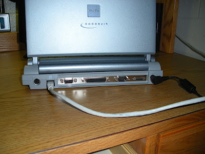
- Fijitsu Port Replicator
- 6-cell extended battery
- Trackpoint w/ 2 buttons

The machine came to me running Windows 2000 Professional edition. Everything worked well with one exception. It was terribly slow and unstable, mainly due to Windows. There was one obvious solution: Install Ubuntu Linux. The machine has no floppy or CD drive, and the BIOS does not support USB booting, so installation of a new OS would be tricky.

The Installation Procedure

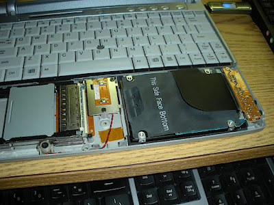
I removed the hard drive from the Lifebook and installed it in an external USB enclosure. I used my Asus eeePC, running Ubuntu, to partition and format the drive as follows: 1GB FAT32, 1GB linux swap, and 27GB EXT4. I then downloaded the mini Ubuntu installation ISO, totaling 12mb, and used Unetbootin to create a bootable partition out of the 1GB FAT32 partition. I installed the hard drive back into the Lifebook. The BIOS booted off the first partition of the hard drive just as it would if the ISO was burn to a CD or flash drive.

It booted into a text based minimal installation menu which prompted for keyboard layout, language, etc, etc. It then configured my wired network adapter and proceeded to download the necessary files from the internet. It installed the newest kernel and the base hardware configuration and drivers required to run . After the installation completed, the machine booted to a command prompt where I updated all the packages and used aptitude to install a GUI based login manager and a very basic Gnome desktop environment.

Hardware

Everything worked upon initial startup excluding the touchscreen. Even my Belkin PCMCIA WIFI card was active and searched for networks.

WIFI

The card was unable to connect to any access point, encrypted or non-encrypted. The signal strength was very low on all networks, even those that were a foot from the machine. I come to find out that it was using the built in kernel driver rtl8180 and that there were some known issues with this driver and the 8185 chipset. I used the ndiswrapper tool to install the windows .inf driver file for the card. In order for this to work, I needed to blacklist the rtl8180 driver from the modprobe configuration file. The blacklist.conf file is located in the /etc/modprobe.d/ folder. I just added an entry to the file that read: "blacklist rtl8180" without the quotations. Once I installed the windows driver, I had to associate the PCI ID of the card with the driver. This was acheived by the command: "sudo ndiswrapper -a devid driver-name, replacing devid with the device ID found by sudo lspci and then sudo lspci -n. To get the card to work, I had to type sudo modprobe ndiswrapper and enter my administrator password. The card came to life and I was able to connect to my network!

Touchscreen

The touchscreen digitizer is connected via a multiplexed PS2 adapter with the trackpoint. After some heavy research, I found that there are some Panasonic ToughBooks that use this same screen digitizer setup. I ran across a forum post that explained how to configure the touchscreen on the Panasonic ToughBook using the Hardware Abstraction Layer and a driver available from the repositories through aptitude. All that I need to do was copy and paste some code into a text file located in the proper location, stated in the forum post, and install the driver software using aptitude. Not only did that install the driver, it also installed a calibration utility that worked like a charm.

Software

I had to install the Gnome power manager, X-marks and Adblock for Firefox, and my favorite web app, Dropbox! If you haven't heard about Dropbox before, have no fear. It is your ultimate sync and save application for all your computers. It gives you 2GB FREE cloud storage space and syncs files from any Mac, Windows, or Linux based PC seamlessly without having to do anything but store the file within the conveniently placed Dropbox folder. Referrals increase both your online storage space as well as the referee's space! If you are interested, give it a go, here is my referral link.

Gnome comes with Firefox, Open Office, Terminal, a text editor, a disk utility, and some other basic administration programs. The stripped down version I installed didn't include anything but the most basic theme, which was what I was looking for. This keeps the memory usage down while being less taxing on the CPU. All in all this is a pretty speedy little machine seeing that it only has 256mb RAM! Linux makes it far more usable. The final product is below.


I hope you enjoyed this post! Feel free to leave a comment. Thanks for reading!!

Friday, March 19, 2010

Repairing a Dell Vostro Power Jack

I recently had a job that involved a broken power jack on a Dell Vostro notebook. The middle barrel of the jack broke and was causing the contacts to touch. When the adapter was plugged in, the jack made a sparking sound and caused the power adapter to short out. The customer was told by Dell and a few other sources that the problem involved the motherboard or the power adapter.

The problem was simply the poorly designed power jack/plug combination whose major fault is the distance the plug sticks out of the machine. This makes it hard to use the machine on any soft surface or tight spaces as pressure is applied to the plug which in turn puts pressure on the jack. Because of the length it sticks out, the pressure applied to the plug is multiplied inside the jack and the solder joints and plastic of the jack become loose and break over time. Symptoms of a broken jack are a loose connection, flickering screen, battery not charging, no power at all, and shorting out the power adapter.

I needed to gain access to the jack. This involved dissembling the notebook down to the motherboard. Most notebooks are put together pretty much the same. There is either an access panel to gain access to the keyboard screws which should expose the LCD, keyboard, WIFI antenna wires, and trackpad connections.

From Dell Vostro power jack repair

Most WIFI cards are under a small access panel found on the bottom of the laptop. Take note of which wire is goes where and unplug them.

From Dell Vostro power jack repair

Remove any screws that hold the keyboard down and unplug it. Unplug the LCD panel and take note of where the wires run. Remove any screws that hold the LCD panel on and remove it.

From Dell Vostro power jack repair

Locate the remaining screws on the bottom of the machine and remove them. These will remove the palm rest and reveal the motherboard and power jack.

From Dell Vostro power jack repair

To keep track of where the screws go I drew the top and bottom of the machine and placed the screws on the diagram.

From Dell Vostro power jack repair

Closeup of the backside of the power jack. The 3 pins in the middle are on the center barrel which completely broke away from the rest of the jack. From repetitive abuse, the contacts on the center barrel bent and were creating a dead short even when the cord was plugged in. I un-soldered the wires and removed the center barrel, straightened out the contacts, and aligned the barrel where it belonged.

From Dell Vostro power jack repair

From Dell Vostro power jack repair

I melted some plastic where plastic had broken out of and secured the rest of it with some epoxy. To ensure that the barrel doesn't move I also epoxied all the contacts to each other as well as the back of the whole jack. Once the barrel was stationary, the jack no longer shorted out the adapter.

From Dell Vostro power jack repair

I re-assembled the notebook to the point where I could test it and plugged it in. The battery began to charge and the machine powered up! I un-pluged it and plugged it back in a few times to ensure it would hold and operate correctly, which it did. I re-assembled the rest of the machine and tested it a few more times. About five hours worth of work and the machine was back up and running! No new motherboard (ahem Dell) and no new power adapter required. The customer was more than happy!

Friday, January 15, 2010

Update on the DIY Digital Picture Frame

In my first post on the frame (found HERE), I discussed using Windows 2000 along with a screen saver application to turn the laptop into a digital picture frame. While this setup worked, it did not stand up to my expectations. The WIFI was sketchy and the machine was very unstable. The software relied on a constant internet connection to fetch pictures from and as soon as the link went down, it was quick to notify the user with an annoying message on the screen. Also, updating pictures was impossible since the connection was down. Something had to be done. A little searching for some DIY software options and other people's projects came up with a plethora of options.

Home screen of McDPF:
From Digital Picture Frame
One sparked my interest, a software set called McDPF. It is based on a linux distribution called DSL (Damn Small Linux) and features a set of applications that work together to provide a simplistic, stable, and functional slideshow that is easily managed from a networked PC. DSL is the "Biz-Card Desktop OS" that only take up 50MB. It was perfect for my application since my frame only had a 4GB hard disk. It would leave me with plenty of storage for pictures. The installation of McDPF was fairly simple! After installing DSL, I copied the backup file for McDPF to my flash drive and booted the machine. After the installation did it's work installing the necessary files, I had to tweak a few settings to make it play nice with DSL. An in-depth explanation of all the installation steps can be found HERE.

Installing DSL:

My work space:

Once all the software configuration was complete, it was time to copy some photos to the frame to test it. Being already connected to my home network and assigned an IP address, I simply typed the frame's IP into a web browser on another computer on the network. This opened the frame's configuration web page, which allowed me to upload photos, turn the screen on or off, change the duration each photo stays on the screen for, or restart the frame. I was also able to connect to the frame's shared folder, which holds the photos, from my Mac to add pictures directly over the network. As soon as I added some photos, the slideshow began! It was working perfectly. The web access isn't completely done yet since the screen schedule isn't working. I was able to adjust the schedule manually from the frame using Cron. More on this HERE. I have it turn the screen on every day at 6:30am and off every night at 10:30. It can be set as specific as each day if you so desire.

Administration webpage:

Manually adjusting the screen schedule:

On to the network connectivity issue. My experience configuring WIFI cards in linux isn't all that great. I had used a wired PCMCIA card for setup and the initial copying of photos. I searched around on the DSL wiki and found a list of verified WIFI cards. A lot of them were older cards using only 802.11B or WEP only. I use WPA2 encryption here and wasn't about to change it just for this. I opted to stick with the wired card and create a wireless bridge using my Linksys WAP-54G bridged with my WRT-54G. This made an extension of my wired network, wirelessly. This took some configuration in the WAP but all went well and the frame was assigned an IP by the WRT. I could have bought a WIFI card and installed it using the ndiswrapper tool and configured the WPA but I took the cheaper (free) route for the time being. It gets the job done!

Testing the bridged link:

To be able to install DSL, I needed access to the CD ROM drive, which was blocked by part of the wooden structure of the frame. I was able to remove the side and gain access to the drive.I cut a slot in the wood to allow access to the CD drive in the future. While I had it partially apart, I figured it necessary to clean it up a little, smooth out some rough edges, and touch up the paint job a little bit. I added angled feet with soft felt feet to raise it up off the table a little and make it a little more stable. Once it was all touched up and the paint was dry, I put it in theliving room, hooked up the wireless bridge, and started everything up. The frame got an IP and I added some more photos. It was an instant hit! Everyone who came through commented on it(as well as on the photos themselves).

CD sot cut out:

Feet:
Frame in the living room, running its slideshow:

I really like the new software! It is lean and very stable.It has been running non-stop since Christmas day without a glitch! I encourage you to give Linux a try, it is very versatile as you can see here!

Thanks for stopping by!